By Craig Zimmermann, P.E.
Like an artist who sculpts with clay or brushes with paints, like an author who writes onto paper the thoughts and ideas floating about in his head, so too that one of the greatest rewards an engineer has is seeing the results of his hard work and design become a reality. To determine a scope, execute a design set of plans, coordinate with many agencies for approvals, and make sure the plans are technically competent and ready to be constructed, well, sometimes the process can be a complex and admittedly a slow process. This sometimes does not jive well with clients who are on exacting schedules. Delays, plan-B scenarios, and on-the-fly decisions are typical in this line of work. Being prepared for these eventualities matter. Dealing with all the many moving parts that need to come together that make up one project is an art onto itself. This is what we do here at REDCOM.
As a professional engineer with experience primarily in site development, I wanted to shed light on a little component of a site we are developing in Washington Township, New Jersey. This little component is actually one HUGE component, one piece of the puzzle of many items that need to be monitored and solved every day. This particular piece is something very important for safety, yet buried underground. Something the general public never really thinks that much about or sometimes even understands!
That’s where the engineering expertise come in.
It took about a year and a half for just this little piece of puzzle to be solved from cradle to grave. And as of end April of 2016, the problem is just about solved. Just a few more buckets of dirt and this piece will literally be buried, forever.
We have, in this case, a five and half acre undeveloped lot. Our client would like to develop the site for the purpose of building an automotive dealership and service center. The location is prime, being on a State highway with lots of visibility and steady traffic.
The situation is such that on this stretch of highway, there is no public water main. So how do we provide water to this site? Well, upfront the answer would seem simple, just dig a new potable well. We did just that.
But what happens if there is a fire? Let’s not forget; as there is no water main on the road, therefore there are no fire hydrants on the road. Typically, you are not going to be able to draw enough water from a well to fight a fire.
Now what?
During the design phase of this project, we had to consider a bunch of things to find an appropriate solution, such as:
- Where is the closet public watermain and hydrant?
- Would the regional water company be amenable to extending a water main near or along our subject property?
- Is there a current plan on place to do so?
- What would be the time involved if a watermain was approved, designed, and built?
- How much would this cost?
- Who would pay for it?
These factors are measured against what the cost would be to have a certain reservoir of water stored on-site, most likely in the form of tank storage. This water would be non-potable, separate from the well, and for the fire department to draw water out of in the event of a fire.
- How big does the tank have to be?
- Where do we get one?/li>
- Who is a reliable vendor and manufacturer?
- What is the lead-time to order one?
- Where would we locate it on-site?
- Aboveground?
- Underground?
By working with the water department and municipality, the determination was eventually made that a watertank would be best suited for the project. There is now a directive and a course of action, but all the questions associated with the tank need be answered and accounted for. We first need to know:
- What is acceptable with the municipality\’s fire officials?
- What codes and standards need to be respected such as what is required by the National Fire Protection Association (NFPA?
Originally we were told we would need an approximate 100,000-gallon tank for this project.
We countered this with in-house calculations and determined that based on the usage of this site, a 35,000-gallon tank would be sufficient, we were eventually approved for such. However, this is still a rather large tank as the following calculation proves;
- 7.48 gallons = 1 cubic foot of water;
- 35,000 gallons = 4,679 cubic feet;
- 4,679 cubic feet equates to roughly a 10 foot diameter tank measuring 64 feet long.
Take a look at the Figure-1 below for the size of this tank, where yours truly was used in the picture for scale:
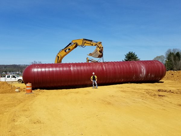
Figure 1- The REDCOM engineer and the watertank, on-site <
So as you can see, the tank is now on-site. But where does it go? And how did we get to this point? Well, let’s now go back and review the history and the tasks.
We had an idea of where it would be going based on the design plans that were approved by the municipality. For our engineering plans, we specified a Xerxes tank in the detail section.
An aboveground location was immediately discounted by the municipality, which was reasonable. Who wants to see a huge tank of this size hanging out somewhere on-site? Even if we had to conceal it somehow, the cost of landscape screening or fencing would be costly. Therefore, we originally had planned for the tank to go underground and near the rear of the property in a permeable area of the site. But this location eventually proved unfeasible for several reasons. The optimum underground location was too close to the building by fire code. This may sound somewhat ironic, but in the event of a fire there must be a certain buffer zone respected so that firetrucks are not parked or people stationed and working too close to a burning building. We also had a somewhat constrictive rear yard setback line and a natural tree line buffer that we were mandated NOT to disturb for residential neighboring lots.
In addition, a shop drawing from the vendor for the tank (Xerxes) was previously submitted by the contractor for engineer approval. A shop drawing is essentially a detailed drawing that lists all the technical specifications of the materials (in this case for the actual watertank as shown in Figure-1 above) that are intended to be purchased, delivered, and used for installation at the site. The engineer compares this shop drawing to the watertank detail located on our engineering plans. This provides an excellent way of essentially cross checking the contractor\’s intent and plan for the watertank with what we, the engineers, have planned and designed for. The shop drawing was approved based on that particular first underground location. See Figure-2 below.
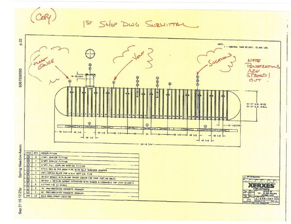
Figure 2- The first watertank shop drawing that was submitted by the contractor. Note penetration points at the tank marked “Float Gauge, Vent, and Suction”. This will prove important later.
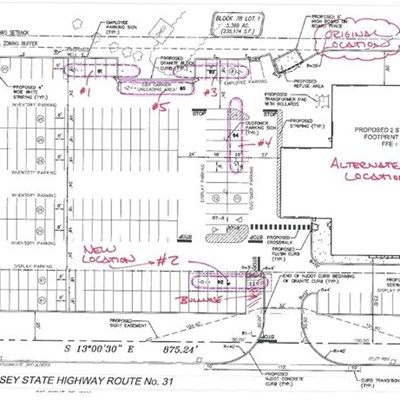
So now we need a new location. A plan of five alternate locations was presented to the fire officials, who met us on site. Together we determined that the best underground location would now be near the front of the property. See Figure-3 below, where the location marked \”#2\” was agreed upon. This location was sufficiently out of the required fire buffer zone and also provided quicker accessibility to the watertank. However, this posed a new problem. The underground location would now be predominantly underneath an impervious (asphalt) display area of parked automobiles.
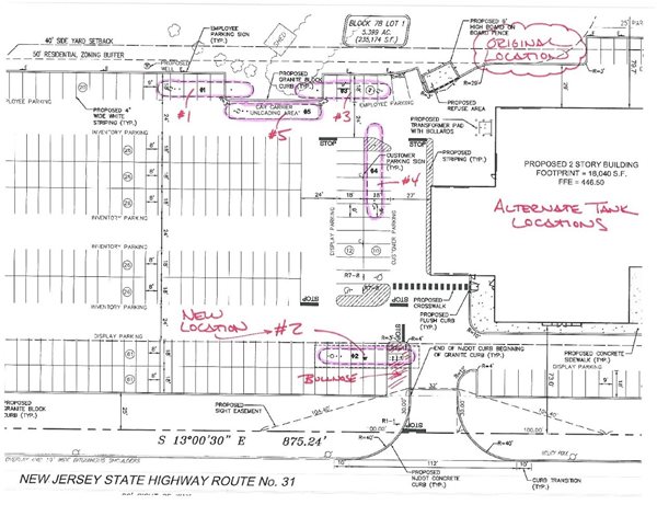
Figure 3 – A plan of the site indicating alternate locations for the watertank. Location #2 was selected at a meeting between REDCOM engineers and the municipal fire inspectors.
The change in location presents another problem for us to solve. There must be a method of drawing water out of the tank in the event of a fire. Three six-inch diameter penetrations into the tank are required and also requested by the Fire Marshall. One is for a draw valve (where a firetruck can connect a pump line into), one is a for a float gauge (to monitor level of water in the tank), and the last is an air vent/stack (to counter any potential pressure build-up). See Figure-4 below for an example of what the Fire Marshall requested which is based on another site in the municipality about a half mile down the road.
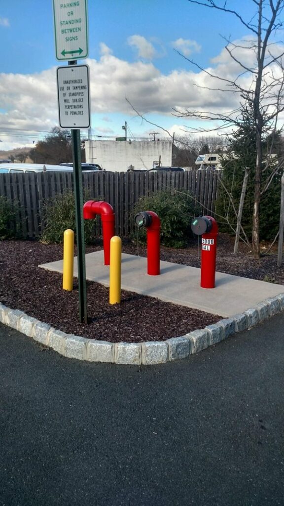
Figure 4 – An example of three penetrations for Suction, Float Gauge, and Air Vent (this watertank is naturally underground)
Recall the first shop drawing for the tank was previously approved for the pervious grassy area where these three penetrations could easily be placed anywhere and without space issues. Now that this tank would be located in an impervious area where the dealership intended to have automobiles parked and on display, you cannot logically have penetrations like what the above Figure-4 indicates – sticking up and out of the asphalt and in the direct way of site vehicular traffic or any parking spots.
Stuck again?
Well, at the chosen \”#2\” location, we had to specifically align these penetrations to be within a small target pervious area that was landscaped and intended as a bullnose curb near the ingress/egress drive of the dealership. This pervious area would be approximately 15 feet in width. The penetration stacks and valves could then be aboveground without any conflicts (other than some landscaping which can be easily adjusted). This required a revision to the original penetrations of the first shop drawing. A call was made to Xerxes, and with their guidance, a second shop drawing would need to be submitted, which would amend and supersede the first shop drawing, which would locate the valve penetrations to align exactly to where this bullnose curb is located. This ultimately will call for a more exact placement of the tank out in the field, and precision will be key.
A second shop drawing is submitted and again, the engineer examines it and approves the tank, this time paying special attention to where the penetrations are located. This required the actual tank to be physically altered as well. The tank was in the process of being built precisely by the approval of the first shop drawing. This is essentially an \’extra\’, as this was an unplanned alteration during the construction process, which cost extra money. The below Figure-5 is the second submitted shop drawing.
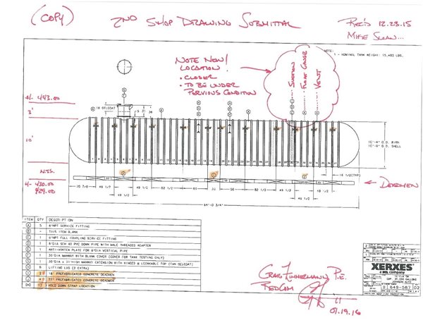
Figure 5- The second watertank shop submittal. Note that the penetrations are specifically placed and aligned.
Now that we have the location of the tank determined, we have our land surveyor stake-out the location of the corners of the pit in which the tank will be placed. We also have the surveyor provide offset stakes to where the penetrations of the tank must go. We have three penetrations of utmost importance, and therefore, three stakes in alignment on both sides of the length of the tank are selected. The surveyor is given our plans so he can precisely determine stake placement by exact coordinates. See Figure 6 below.
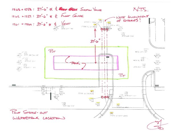
Figure 6- The survey stake-out for the watertank. Note the 3 sets of stakeout points, in parallel, where the penetrations must be located.
Now knowing the location, we can now instruct the site contractor to start digging the pit hole in which the tank is going to go.
Take a look at Figures 7-9 to see the size and depth of the pit that had to be dug!
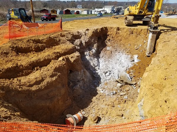
Figure 7- The watertank pit hole being dug out. Note that we also unearthed an orange safety barrel!
Note also the extreme amount of rock in which the contractor had to hammer-jack though. Figure 7 also clearly represents the depth of the pit (approximately 14 feet deep). This Figure illustrates the pit at approximately 50% completeness. Also if you look closely, you can see near the upper left corner three of the stakes (with blue ribbons) that are for the penetration alignment.
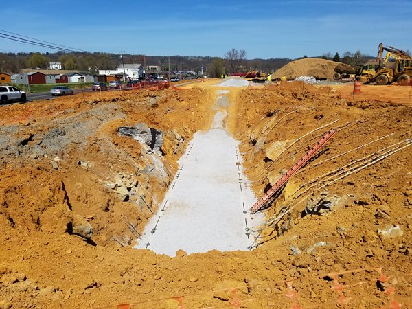
Figure 8- The pit, bedded and complete and ready to receive the watertank.
The pit took about two weeks of hammering and digging to get it to the appropriate size and shape. Note in Figure-8 the approximate 3 to 1 grading on both sides of the pit. This is primarily a safety precaution to prevent cave-ins. Figure-8 also shows an “access ramp” for workers to get down into the pit safely.
This bottom of the pit is a gravel fill bedding for the tank and if you look closely, you can see two concrete “deadmen” rows that parallel either side of the bedding, as well as straps attached at galvanized anchor points to the “deadmen” along the right side.
So now the day has finally come for the tank to be delivered on-site! We got lucky and had a beautiful April day. The tank comes directly off a flatbed truck, and for vehicular highway safety, requires two car escorts. See Figure-9 below.
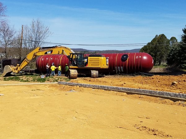
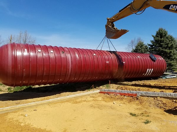
Figure 10 – Thats a lot of tank! 15,400 pounds (7.7 tons) being lifted by the CAT bulldozer.
So now if you go back and reference Figure-1 (the picture with yours truly in it), you will see we are now up to speed on all the events in regards to the tank.
Now we must get this tank IN the pit and placed exactly right, both in depth and horizontally. Recall how important the alignment of the penetration valves is going to be.
The CAT bulldozer has done its job and now a mobile gantry crane (pictured in the right upper corner) takes over for the precise placement of the watertank.
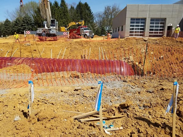
Figure 12 – the tank and the alignment stakes (in foreground and background).
Essentially, each stake represents one valve penetration and if you look closely, you can see the tank, with slight incline, about ready for touchdown, with the valves aligned to the stakes. Once this tank is covered up, the bullnose curb will be directly above the tank at this location.
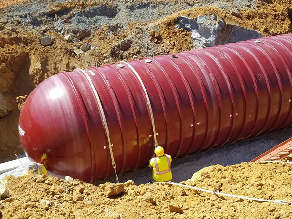
Figure 13 – A worker straps the tank down, to prevent floatation.
Remember previously when I posed the question on what the straps are for? These straps are anti-floatation straps. They are strung over the tank at specific points (12 in all). A turnbuckle on the other side connects the strap to the opposing “deadmen” and tightened down. In the design process, we had to supply information to Xerxes on soil conditions, depth, size of tank, etc, so that they can prepare safety calculations that allot for bearing pressure, soil stresses, and buoyancy. This watertank obviously is intended to be full of water. In the event of a fire, pressure would be lost within the tank and/or air volume would replace the water. This causes a buoyancy, so the tank is strapped down to counter this effect.
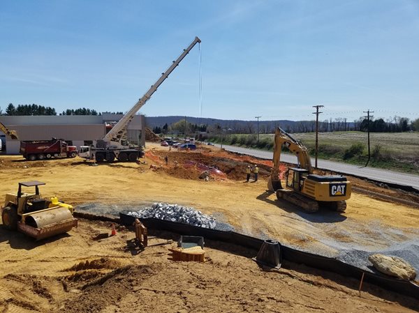
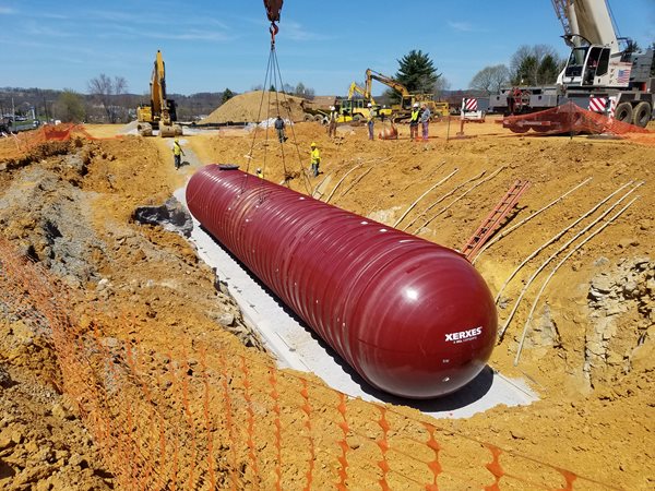
Figure 14 – Check it out! Touchdown! The tank in the middle of the pit. Note the building in the background left and the people and equipment, all for scale!
Speaking of water, here is a quick idea of approximately how much this tank will weigh “in-the-ground” when full of water:
- Tank tare weight = 15,400 pounds;
- One gallon of water = 8.34 pounds;
- 35,000 gallons of water = 291,900 pounds;
- 15,400 pounds (tare) + 291,900 pounds (water) = 307,300 pounds;
- 2000 pounds = 1 ton;
- 307,300 pounds = 153.65 tons!
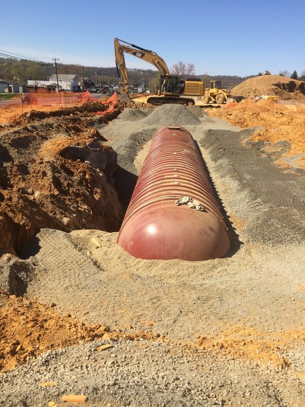
Figure 15 – The tank, being backfilled and buried.
One of the last things to do, as Figure 15 illustrates, is to backfill the area around the tank. Clean select fill is imported in from off-site and filled in layered lifts of 12”depth or so. Each “lift” is tamped and packed into the ground and around the tank in this fashion. You can see on the top of the fill the tracks of the vibratory machine as it tamped the fill in-place. This baby is going no-where!
So as you see, the watertank is but one item of hundreds if not thousands of items required to be monitored and accounted for all through the planning, design, approval, and construction phases on any development project.
Here at REDCOM, we are a design-build construction company with experience in the development of many commercial sites, not only in New Jersey but in Connecticut, and other states as well. We are used to handling these tasks efficiently and with professionalism and love when an interesting challenge comes along!
Please take a moment to peruse our website for other examples of previously designed and built projects. We strive to succeed for one reason: so that your project succeeds. Have a project like this you would like to have built? Find us. We are committed, dedicated, and ready to help you.

Craig Zimmerman is a professional engineer who has been licensed in the state of New Jersey since 2006. His focus is primarily site engineering and development. Craig has been involved in many projects from single residential lots and subdivisions to multi-phased, multi-acre mixed use developments, big box commercial properties, educational institutions, and urban redevelopment. He also has professional experience in land surveying, traffic, sanitary, and municipal engineering. He attended the Pennsylvania State University and has a Bachelor of Science Degree in Environmental Engineering. He is an active 4th level black belt in Isshin-ryu karate and also enjoys mountain bike riding and hiking. He roots for the Yankees and Jets. You will normally find him involved in all things theatre as director, actor, stage manager, or set designer, and has served many years on various theatre boards. Craig lives in Rockaway, New Jersey. Contact him at: [email protected]
Visit http://www.xerxes.com/ for more information on their fine products (and representation; believe me, they were most knowledgeable and helpful all through the process)
